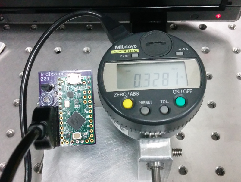
Mitutoyo dial indicators can measure small displacements down to micron levels. I use them to calibrate motors used in quantum optics experiments, where every micron is several femtoseconds in the life of a photon. Modifying the instructions and source code in this instructable on communicating with the Mitutoyo communication protocol from arduino, I was able to use a teensy to automate this calibration process.
My modifications/improvements to the original instructable are:
- creating a PCB for the teensy
- handling units and sign
- adding a SCPI interface
- creating a python example script using InstrumentKit
The code and Eagle files for this project are available on github.

Electrical Inferface
The electrical interface between the teensy and the Mitutoyo cable are relatively unchanged. The teensy footprint was adapted from footprints teensy originally created by PRJC forum user Constatin. The PCB was printed using OSH Park. I use a Teensy LC, but I believe the PCB and source code will work with all Teensy models. The other parts required to complete the board are:
- a 10 kOhm R0805 surface mount resistor
- a 2N2222 transistor
- an 8 pin header (digikey part number ED1543-ND)
Teensy (embedded) Code
The main.ino for this project is similar to the code in the instructable, but with a few bug fixes and code organization.
#include "scpi_comm.h"
#include "struct_definitions.h"

mitutoyo_interface _interface = {.acknowledge = 0, .number = 0L, .sign = 0,
                                 .decimal = 0, .units = 0};

int req = 5; //mic REQ line goes to pin 5 through q1 (arduino high pulls request line low)
int dat = 2; //mic Data line goes to pin 2
int clk = 3; //mic Clock line goes to pin 3


byte mydata[13];

void setup() {
    Serial.begin(9600);
    pinMode(req, OUTPUT);
    pinMode(clk, INPUT_PULLUP);
    pinMode(dat, INPUT_PULLUP);
    digitalWrite(req, LOW); // set request at LOW
}

void loop() { // get data from mic
    digitalWrite(req, HIGH); // generate set request
    for(int i = 0; i < 13; i++ ) {
        int k = 0;
        for (int j = 0; j < 4; j++) {
            while( digitalRead(clk) == LOW) { } // hold until clock is high
            while( digitalRead(clk) == HIGH) { } // hold until clock is low
            bitWrite(k, j, (digitalRead(dat) & 0x1)); // read data bits, and reverse order
        }
        // extract data
        mydata[i] = k;
        _interface.sign = mydata[4];
        _interface.decimal = mydata[12];
        _interface.units = mydata[11];
    }

    // assemble measurement from bytes
    char buf[7];
    for(int lp = 0;lp < 6; lp++ )
    {
        buf[lp]=mydata[lp+5]+'0';
    }
    buf[6] = 0;
    _interface.number = atol(buf);
    if (Serial.available() > 0) {
        comm_protocol(Serial.read(), &_interface);
    }
}
My SCPI interface code, in scip_comm.h is similar to the code for my optical switch. Also like the optical switch code, I store variables generated in the main loop to an interface struct:
typedef struct{
    bool acknowledge;
    long number;
    int sign;
    int decimal;
    int units;
    } mitutoyo_interface;
Python (Computer) Code
The serial communication is handled using an InstrumentKit instrument.
The dial indicator will respond with either millimeters or thousandths of an inch depending on an internal setting. Though with the original code, this might have resulted in unit conversion errors. However, by converting the reading string to a quantities Quantity, we can use someone else’s unit conversion code.
    @property
    def reading(self):
        """
        Get the current reading off of the indicator.

        :type: `~quantities.Quantity`
        :units: millimeters or mils
        """
        query = self.query("READ?").split(" ")

        response = pq.Quantity(float(query[0]), query[1])
        return response
Finally, we can grab readings whenever we want using:
if __name__ == "__main__":
    mi = MitutoyoInterface.open_serial(vid=5824, pid=1155, baud=9600)
    while True:
        print(mi.reading)