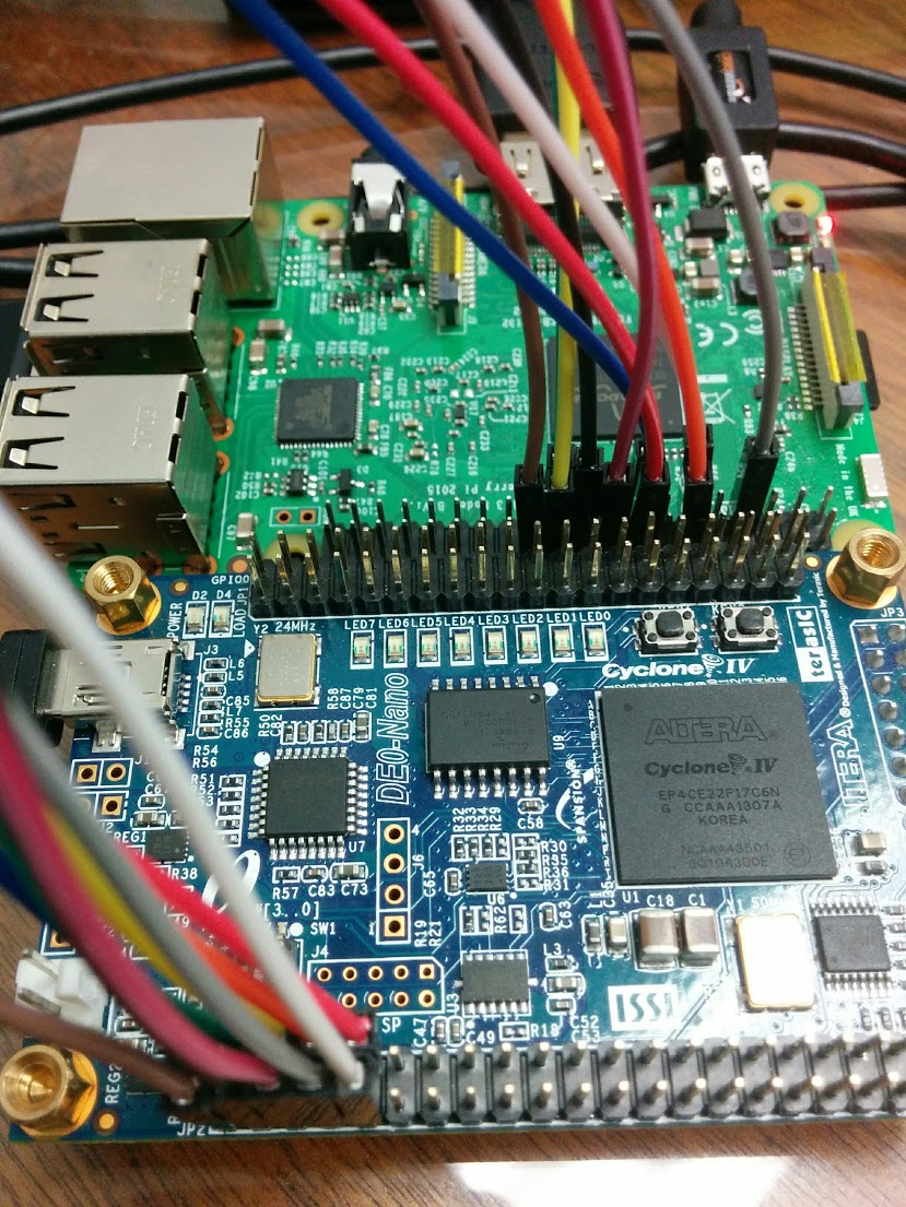
I’ve written some basic sample code for communicating between an FPGA and a raspberry pi, with both serial and parallel examples. The demo project pulls x, y, and z accelerometer data off of the DE0-Nano Terasic Altera Cyclone IV development board and prints it to the terminal in the Raspberry Pi. This post goes over setting up the examples and explains some of the code.
Functionality Common to Both Examples
The verilog and tcl common to both DE0-Nano projects is in de0nano/common
The accelerometer puts out 16 bits of data for each of the three dimensions. The basic functionality of both examples is that the Raspberry Pi puts out one of the bytes for ‘x’, ‘y’ and ‘z’, and the DE0-Nano responds with two sequential bytes, one for the lower half of the 16 bits, one for the upper half. The accelerometer verilog code comes from Terasic, but with a modified module which includes the 2-bit input register called dimension. When dimension is 0, the axis to be read is x, 1 is y and 2 is z. This is accomplished by setting the hex values sent to the accelerometer using ternary operators in spi_ee_config.v:
wire[5:0] LB = (dimension==0) ? X_LB: ((dimension==1) ? Y_LB: Z_LB);
wire[5:0] HB = (dimension==0) ? X_HB: ((dimension==1) ? Y_HB: Z_HB);
The 50 MHz clock, accelerometer pins, reset button, and LEDs are all defined in the file common_pins.tcl.
Both examples use a simple state machine to handle responding to incoming signals. It looks like this:
The check signal for each example is different for both examples; in the serial example, it’s either read in data being ready, or the transmission line being free, in the parallel example, it’s the incoming clock pin from the Raspberry Pi. Here’s the verilog for this state machine for the serial example:
always @(posedge (TxD_busy | RxD_data_ready))
    if(write_state == 0)
        begin
            if(120 <= RxD_data <= 122)
                write_state = 1;
            if(RxD_data == 120)
                dimension = 0;
            else if(RxD_data == 121)
                dimension = 1;
            else if(RxD_data == 122)
                dimension = 2;
        end
    else if(write_state == 3)
        write_state = 0;
    else
        write_state = write_state + 1;
Serial Example
Setup
- Plug GPIO03 on the DE0-Nano into GPIO 15 on the Raspberry Pi.
- Plug GPIO05 on the DE0-Nano into GPIO 14 on the Raspberry Pi.
To load the DE0-Nano, can either import the verilog and tcl files into your own quartus project, or use my pyquartus tool. To compile and upload using pyquartus, plug your DE0-Nano into your computer, and run:
cd de0-nano-raspi-serial-demo
pyquartus -c -u -i de0nano/common -p de0nano/serial
On the raspberry pi side, install the requirements and run the program by opening up a terminal and running the commands:
cd de0-nano-raspi-serial-demo/raspi
pip install -r requirements.txt
python serial/main.py
Code
The serial verilog code was adapted from Jean P Nicolle at fpga4fun. I’ve made some modifications to it, including separating the modules and creating a header file to define a common baud rate in parameters.h:
parameter BAUD_RATE  = 460800;
parameter CLK_FREQUENCY = 50000000;
The example requires two state machines - one to handle the transitions between read to write, one to handle setting the output data. This is because the TxD_data_ready is used as a signal for transitions between read and write and thus can’t be set by the same state machine it drives. A second state machine drives TxD_data_ready and the data:
always @(write_state)
    if (~TxD_busy)
        if(write_state == 1)
            begin
                TxD_data_ready = 1'b1;
                TxD_data <= data[7:0];
            end

        else if(write_state == 2)
            begin
                TxD_data_ready = 1'b1;
                TxD_data <= data[15:0];
            end
        else if(write_state == 3)
            begin
                TxD_data_ready = 1'b0;
            end
    else if(TxD_busy)
        begin
            TxD_data_ready = 1'b0;
        end
The Raspberry Pi side is driven by python using the pyserial library:
from time import time
from sys import argv
from serial import Serial

rate = argv[1]
if rate != 0 and rate != 1:
    rate = 0

rates = [460800, 115200]

print("setting rate to: ", rates[rate])

conn = Serial('/dev/ttyAMA0', baudrate=rates[rate], timeout=2)


def read_dimension(dimension):
    global conn
    failure_count = 0
    # the serial connection often fails to read two single bytes
    while True:
        try:
            conn.write(dimension)
            value = ord(conn.read(1))
            value += ord(conn.read(1)) << 8
            return value
        except Exception as e:
            failure_count += 1

if __name__ == "__main__":
    while True:
        start = time()
        x_val = read_dimension(b'x')
        y_val = read_dimension(b'y')
        z_val = read_dimension(b'z')
        print(x_val, y_val, z_val, time()-start)
Parallel Example
Setup
- Plug GPIO 133 on the DE0-Nano into GPIO 8 on the Raspberry Pi
- Plug GPIO 131 on the DE0-Nano into GPIO 10 on the Raspberry Pi
- Plug GPIO 129 on the DE0-Nano into GPIO 24 on the Raspberry Pi
- Plug GPIO 127 on the DE0-Nano into GPIO 4 on the Raspberry Pi
- Plug GPIO 125 on the DE0-Nano into GPIO 17 on the Raspberry Pi
- Plug GPIO 132 on the DE0-Nano into GPIO 22 on the Raspberry Pi
- Plug GPIO 130 on the DE0-Nano into GPIO 9 on the Raspberry Pi
- Plug GPIO 128 on the DE0-Nano into GPIO 25 on the Raspberry Pi
- Plug GPIO 126 on the DE0-Nano into GPIO 18 on the Raspberry Pi
- Plug GPIO 124 on the DE0-Nano into GPIO 23 on the Raspberry Pi
To load the DE0-Nano, can either import the verilog and tcl files into your own quartus project, or use my pyquartus tool. To compile and upload using pyquartus, plug your DE0-Nano into your computer, and run:
cd de0-nano-raspi-serial-demo
pyquartus -c -u -i de0nano/common -p de0nano/parallel
On the raspberry pi side, install the requirements and run the program:
cd de0-nano-raspi-serial-demo/raspi
pip install -r requirements.txt
python parallel/main.py
Code
On the parallel example, the Raspberry Pi does the heavy lifting. It uses a pin for clock, a pin to indicate whether the data pins are being used for reading and writing, and then 8 pins for data. This is accomplished using the RPi.GPIO python library:
def send_byte(byte_out):
    """
    Send a single byte.
    """
    GPIO.output(clock_pin, 0)
    # set the chip select to write
    GPIO.output(chip_select, 1)
    # send the byte
    values = [(ord(byte_out) >> i) % 2 for i in range(0, 8)]
    GPIO.setup(data_pins, GPIO.OUT)
    GPIO.output(data_pins, values)
    # flash the clock pin
    GPIO.output(clock_pin, 1)
    GPIO.output(clock_pin, 0)


def get_byte():
    """
    Get a single byte.
    """
    GPIO.setup(data_pins, GPIO.IN)
    # read the data pins
    GPIO.output(chip_select, 0)
    GPIO.output(clock_pin, 1)
    GPIO.output(clock_pin, 0)
    value = 0
    for i in range(0, 8):
        value += GPIO.input(data_pins[i]) << i
    return value
In verilog, the code is pretty simple and can be accomplished with a ternary operator and some logic triggered by the clock:
module parallel_txrx(
    input clock,
    input chip_select,
    inout [7:0] data_pins,
    output reg [7:0] data_in,
    input [7:0] data_out
);

reg [7:0] data_out_internal;

assign data_pins = chip_select ? 8'bZ : data_out_internal;

always @(negedge clock)
    // if chip select is high, the fpga is reading in data
    if(chip_select)
        data_in <= data_pins;
    else
        data_out_internal <= data_out;

endmodule
I use the negative edge of the clock signal to ensure the data pins on the Raspberry Pi are synchronized and ready.
Performance
The parallel example takes ~60 microseconds to send and receive a byte, and ~25 microseconds to receive a byte. That results in a transmission speed of ~133kHz if sending and receiving is required, and ~320kHz if only receiving data.
The serial example can transmit at 460800 baud, however, after about a second of communication, the Raspberry Pi and FPGA stop communicating. I’m not exactly sure why this happens, but running the verilog code with a teensy serial interface is much more stable.
In both of these cases, it might be possible to get faster and more reliable performance by switching to c.