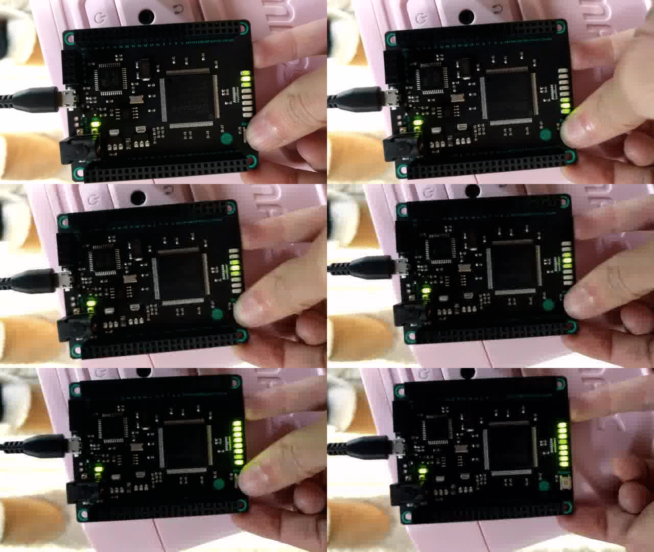
CλaSH is a neat cross compiler from Haskell to VHDL, Verilog and SystemVerilog. Most examples were tested on an Altera FPGA (the DE0-Nano), and not Xilinx (the other major FPGA producer). This blog post demonstrates the procedure for getting Haskell code running on a Xilinx FPGA, which is as (relatively) straightforward as the Altera versions.
Specifically, these instructions are for the Embedded Micro Mojo, which is by far the best Xilinx development board.
Tools Setup
- Follow the CλaSH instructions for installing haskell, cabal and clash. CλaSH needs a specific version of haskell, so if you don’t follow their instructions you’re going to have a bad time.
- Follow Embedded Micro’s instructions for installing the Xilinx verilog compiler
- On linux, add the mojo’s udev rules
- Download and install the Mojo loader
Project Setup
First, generate some verilog from the blinker.hs example.
Start from the embedded micro sample base project. Remove the mojo_top.v file and add the verilog generated by CλaSH.
It will complain that there is no code defining the altpll50 module! The verilog written by CλaSH expects a clock generated by the Altera ALTPLL MegaFunction. To generate a clock that is similar in Xilinx, follow these steps:
- Open up the Xilinx Core Generator (Tools -> Core Generator)
- In Core Generator, open your current project (under File -> Open Project and picking the mojo_top.prj file.
- Make sure the chip is set to your spartan-6 chip. (for the mojo 2 board, this is XC6SLX9-2tqg144)
- Double click on Clocking Wizard in the IP catalog.
- Call the component altpll50, and change the input clock frequency to 50 MHz. On the next screen, change the output clock to 50 MHz
- On page 5 of the process, change the names of the inputs and outputs to match the Altera version. CLK_IN1 -> inclk0, CLK_OUT1-> c0, RESET -> areset, and LOCKED -> locked
- Wait for the Core Generator to make your verilog, then add it to your project using Project -> Add Sources. The altpll50.v should be in your top project directory. Do not add the UCF file!
Change the User Constraints File (.ucf) should be:
NET "CLOCK_50<0>" TNM_NET = clk;
TIMESPEC TS_clk = PERIOD "CLOCK_50<0>" 50 MHz HIGH 50%;
NET "CLOCK_50<0>" LOC = P56 | IOSTANDARD = LVTTL;
NET "KEY1" LOC = P38 | IOSTANDARD = LVTTL;
NET "LED<0>" LOC = P134 | IOSTANDARD = LVTTL;
NET "LED<1>" LOC = P133 | IOSTANDARD = LVTTL;
NET "LED<2>" LOC = P132 | IOSTANDARD = LVTTL;
NET "LED<3>" LOC = P131 | IOSTANDARD = LVTTL;
NET "LED<4>" LOC = P127 | IOSTANDARD = LVTTL;
NET "LED<5>" LOC = P126 | IOSTANDARD = LVTTL;
NET "LED<6>" LOC = P124 | IOSTANDARD = LVTTL;
NET "LED<7>" LOC = P123 | IOSTANDARD = LVTTL;
Notice that KEY0 is missing. The Mojo board has only one button, instead of the DE0-Nano’s two. In the original example, button 0 is used to reset the clock and button 1 is used to invert the state. I’ve decided to set the reset to constant low and set the Mojo’s one button to button 1:
altpll50_2 altpll50_inst
  (.inclk0 (CLOCK_50[0])
  ,.c0 (system1000)
  ,.areset (1'b0)
  ,.locked (altpll50_locked));
In addition, there are a few changes that need to be made because of the way Xilinx handles verilog. Hopefully these can be incorporated into CλaSH in the future:
- change the round brackets around CLOCK_50(0) to CLOCK_50[0], same for KEY1
- Xilinx does not like using NOT in wire assignments. If you want to use an inverted signal, simply create an inverted wire, i.e.:
wire not_reset = ~reset;
my_mod my_mod_inst(.reset(not_reset));
Compilation and Upload
Now your project is ready to run! Under processes, right click on Generate Programming File and select run. If you can’t find this option, make sure that you’ve selected the file blinker.v and that it is set as the top module (right-click on blinker.v and set as top module).
If you get a translation error about Symbol ‘MMCM_ADV’ is not supported in target ‘spartan 6’, it means the wrong chip was selected in the clock generation step.
Once it completes successfully, load the generated *.bin file onto the mojo using the Mojo Loader
End Result

Thanks for putting up with the camera shake, my tripod is in Florida